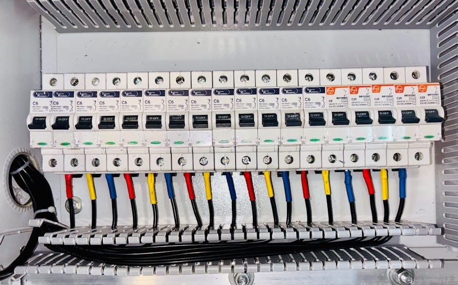
3-way switches enable control of a single light fixture from two locations, ideal for hallways or staircases. Wiring diagrams provide a clear visual guide for installation, ensuring safety and proper connections. This section introduces the fundamentals of 3-way switch wiring, emphasizing the importance of diagrams for successful setups.
1.1 Understanding the Basics of 3-Way Switches
A 3-way switch allows control of a single light fixture from two different locations, making it ideal for hallways, staircases, or large rooms. Unlike a standard switch, it uses traveler wires to connect the two switches, enabling the light to be toggled from either location. The common terminal is key, as it connects to the power source or the light fixture. Wiring diagrams simplify installation by illustrating how these components interact, ensuring proper connections and safe operation. Understanding this setup is crucial for successful 3-way switch installations.
1.2 Importance of Wiring Diagrams for 3-Way Switches
Wiring diagrams are essential for installing and troubleshooting 3-way switches. They provide a clear visual representation of the circuit, making it easier to understand how the power, traveler, and ground wires connect. These diagrams help identify components like the common terminal, traveler wires, and ground wire. By following a wiring diagram, you can avoid errors, ensure safe connections, and comply with electrical standards. They also serve as a valuable resource for diagnosing issues, such as faulty connections or incorrect wire color coding, saving time and reducing the risk of electrical hazards.

Components of a 3-Way Switch
A 3-way switch has four terminals: common (usually brass), two travelers (often brass or silver), and ground (green). Wires include black (hot), white (neutral), copper (ground), and red (traveler) wires.
2.1 Terminal Identification (Common, Traveler, Ground)
A 3-way switch features four terminals: common (brass), two traveler (brass/silver), and ground (green). The common terminal connects to the power source or fixture. Traveler terminals link the two switches, allowing the electrical signal to pass between them. The ground terminal ensures safety by connecting to the grounding system. Identifying these terminals correctly is crucial for proper wiring and functionality of the switch. Always refer to the wiring diagram for accurate connections.
2.2 Color Coding of Wires (Hot, Neutral, Ground)
In a 3-way switch wiring setup, wires are color-coded to simplify identification. The black wire is typically the “hot” wire, carrying electrical current. The white wire serves as the neutral, completing the circuit. The green or bare copper wire is the ground, ensuring safety by connecting to the grounding system. These color codes are standardized to prevent confusion during installation. Always refer to the wiring diagram to ensure correct connections, as proper wire identification is critical for safe and functional circuit operation.

Common 3-Way Switch Wiring Configurations
3-way switches can be wired in various configurations, such as power at the light or using a 4-way switch. Diagrams guide installers through each setup, ensuring proper connections and functionality.
3.1 Light Between Switches Configuration
In this setup, the light fixture is installed between the two 3-way switches. Power is typically supplied to the first switch, then connected to the light, and finally to the second switch. The traveler wires carry the electrical signal between the switches, enabling control from both locations. A wiring diagram for this configuration clearly illustrates the connections, ensuring that the hot, neutral, and ground wires are properly linked to avoid electrical hazards and ensure smooth operation.
3.2 Power at the First Switch Configuration
In this configuration, power is supplied directly to the first 3-way switch, which then connects to the light fixture and the second switch. The traveler wires carry the electrical signal between the switches, enabling control of the light from both locations. This setup is common in hallways or staircases, where dual control is essential. A wiring diagram for this configuration clearly illustrates how the hot, neutral, and ground wires are connected, ensuring safe and proper installation. This method is straightforward and widely used for its reliability and simplicity.
3.3 Power at the Light Fixture Configuration
In this setup, power is supplied directly to the light fixture, which then connects to the first 3-way switch. From there, the circuit continues to the second 3-way switch. This configuration is useful when the light fixture is the central point of the circuit. The wiring diagram illustrates how the hot, neutral, and ground wires are connected, ensuring proper installation. This method is less common but effective for specific installations where the fixture serves as the power source. It provides a reliable way to control the light from two locations while maintaining safety and functionality.

Wiring Diagrams and Their Interpretation
Wiring diagrams provide a visual representation of connections, using standard symbols for switches, lights, and wires. They ensure accurate installations and safe troubleshooting processes.
4.1 How to Read a 3-Way Switch Wiring Diagram
Reading a 3-way switch wiring diagram involves identifying symbols like switches, lights, and wires. Start by locating the power source, typically marked as “HOT” or “LIVE.” Trace the wires connecting the switches and the fixture. Understand that traveler wires link the switches, while the common terminal connects to the light. Color codes help differentiate between hot, neutral, and ground wires. Follow the flow of electricity to ensure connections align with the diagram. Always verify the setup matches your specific wiring configuration before proceeding.
4.2 Common Symbols Used in Wiring Diagrams
Wiring diagrams use standardized symbols to represent components. A 3-way switch is often shown with three terminals: common, traveler, and ground. A light fixture is typically depicted as a circle with a vertical line inside. Wires are represented by lines, with colors indicating their purpose: black for hot, white for neutral, and green or bare for ground. These symbols are universal, making diagrams easy to interpret. Understanding them is essential for accurately wiring a 3-way switch configuration and ensuring safe, functional connections.
Safety Precautions and Best Practices
Always turn off power at the circuit breaker before starting work. Use a voltage tester to confirm wires are de-energized. Install GFCI outlets for added safety. Ensure proper grounding and follow local electrical codes. Consult a licensed electrician if unsure about any step.
5.1 Essential Safety Tips for Wiring a 3-Way Switch
- Always disconnect power at the circuit breaker before starting work.
- Use a voltage tester to confirm wires are de-energized.
- Ensure proper grounding to prevent shocks or fires.
- Install GFCI outlets in moisture-prone areas for added safety.
- Follow local electrical codes and manufacturer guidelines.
- Use insulated tools to prevent accidental contact with live wires.
- Double-check connections before restoring power.
- Consult a licensed electrician if unsure about any step.
Adhering to these safety practices ensures a secure and successful 3-way switch installation.
5.2 Tools and Materials Required
To wire a 3-way switch, you’ll need specific tools and materials. Essential tools include a screwdriver, wire strippers, needle-nose pliers, and a voltage tester. Materials required are 3-way switches, 14- or 12-gauge wires (black, white, red, and copper ground), wire connectors, and electrical boxes. Additionally, a wiring diagram is crucial for guidance. Ensure all components meet local electrical codes and are suitable for your setup. Proper tools and materials ensure a safe and efficient installation process.

Troubleshooting Common Issues
Common issues include faulty connections and lights not functioning or flickering. Use wiring diagrams to trace circuits and identify problems. Verify wire colors and switch terminals and ensure proper connections.
6.1 Identifying and Fixing Faulty Connections
Faulty connections are a common cause of 3-way switch issues. Start by verifying all wire connections using a wiring diagram to ensure correctness. Check for loose screws, oxidized terminals, or incorrect wire assignments. Use a multimeter to test continuity between traveler wires and confirm the common terminal connections. If a switch is malfunctioning, replace it with a new one, carefully matching the terminal configurations. Properly secure all wires to avoid future disconnections and ensure reliable operation of the lighting system.
6.2 Resolving Light Flickering or Non-Functioning Issues
Light flickering or non-functioning issues often stem from incorrect wiring or loose connections. Verify the wiring against a 3-way switch diagram to ensure proper configuration. Check for damaged or frayed wires and replace them if necessary. Use a multimeter to test for power at the switch and fixture. If the light flickers, ensure traveler wires are securely connected and not crossed. Consult the diagram to confirm the common terminal is correctly linked to the power source. Addressing these issues typically resolves most lighting problems.
Downloading and Using 3-Way Switch Wiring Diagrams
3-way switch wiring diagrams are available as downloadable PDFs from official manufacturer websites and hardware stores. These resources provide clear visual guides for understanding connections, ensuring safe and correct installation.
7.1 Sources for Free 3-Way Switch Wiring Diagram PDFs
Free 3-way switch wiring diagram PDFs are available from reputable sources like manufacturer websites, hardware stores, and DIY forums. Websites such as Leviton, Lutron, and Home Depot offer downloadable guides. Additionally, platforms like Instructables and Pinterest provide visual tutorials. These resources include detailed diagrams for various configurations, such as power-at-the-light or power-at-the-switch setups. They are essential for DIYers and electricians, ensuring accurate and safe installations. Always verify the source to ensure compliance with local electrical codes and standards.
7.2 How to Apply the Diagram to Your Specific Setup
To apply a 3-way switch wiring diagram to your setup, start by identifying your specific configuration—whether power enters at the first switch, the light fixture, or another location. Match the diagram’s layout to your setup, ensuring correct wire connections for travelers, common terminals, and ground wires. Label wires to avoid confusion and double-check connections before powering up. If unsure, consult the diagram for visual guidance or seek additional resources for clarification. Always turn off power at the circuit breaker before starting work.
Understanding 3-way switch wiring diagrams is crucial for safe and effective installations. By following these guides, you can confidently manage light control in various configurations, ensuring reliability and functionality in your electrical setups.
8.1 Summary of Key Points
3-way switch wiring diagrams are essential for controlling lights from multiple locations. They provide clear visual guides for installing and troubleshooting circuits. Understanding terminal identification, wire color coding, and common configurations ensures safe and effective setups. Always follow safety precautions and use appropriate tools. Diagrams help identify faulty connections and resolve issues like flickering lights. Downloading PDF resources and applying them to specific setups simplifies the process. Proper installation enhances functionality and reliability in residential or commercial environments.
8.2 Final Tips for Successful Installation
Ensure power is off before starting work. Use a voltage tester to confirm no live wires. Follow the wiring diagram meticulously, double-checking connections. Secure all wires tightly to terminals to avoid loose links. Test the setup by toggling switches to ensure proper light operation. If unsure, consult a licensed electrician. Keep all tools and materials organized for efficiency. Regularly review safety guidelines to maintain a secure working environment. Proper planning and attention to detail guarantee a reliable and long-lasting installation.